Building a Keyboard with tscircuit
Overview
This tutorial guides you through creating a custom mechanical keyboard PCB using tscircuit. We'll cover setting up your environment, understanding the core components, building a key matrix, creating a simple 4-key keyboard, and finally scaling up to a standard 60% layout using data from Keyboard Layout Editor.
We'll be using a Raspberry Pi Pico as the microcontroller, Kailh Choc-style key switches, and standard diodes for the matrix.
1. Set Up Your Environment
Before we start building, let's get your development environment ready.
Prerequisites
You need Node.js or Bun installed on your system.
Install tscircuit CLI
Install the tscircuit command-line interface (CLI) globally using npm or bun:
npm install -g @tscircuit/cli
# or
bun install -g @tscircuit/cli
This installs the tsci command, which you can use to create, develop, and export tscircuit projects.
Create a New Project
Navigate to where you want to create your project and run tsci init:
mkdir my-keyboard
cd my-keyboard
tsci init
This command bootstraps a new tscircuit project with a basic structure, including an index.tsx file (our main circuit definition), package.json, tsconfig.json, and other necessary configuration files.
Run the Development Server
Start the tscircuit development server by running:
tsci dev
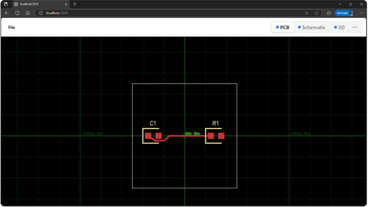
This command compiles your index.tsx file and serves it on http://localhost:3020 (or the next available port). Open this URL in your browser. You should see a live preview of your circuit, including PCB, Schematic, and 3D views. The server watches for file changes and automatically updates the preview.
2. Import the Main Components
A keyboard PCB primarily consists of three types of components:
- Microcontroller: The "brain" that scans the keys and communicates with the computer. We'll use a Raspberry Pi Pico.
- Key Switches: The physical buttons you press. We'll use a generic Kailh Choc footprint component.
- Diodes: Prevent "ghosting" (incorrect key press readings) in the matrix.
Let's import these into our project.
First, you'll need to install the packages containing the Pico and Key components:
tsci add @tsci/seveibar.PICO @tsci/seveibar.Key
Now, let's import and preview each component to see what we're working with:
Microcontroller (Raspberry Pi Pico)
We import the PICO component. It provides the necessary footprint and pin definitions for the Raspberry Pi Pico.
import { PICO } from "@tsci/seveibar.PICO";

export default () => (
<board width="50mm" height="60mm">
  <PICO name="U1" />
</board>
);
Hot-Swappable Key Switch (Kailh Choc Style)
We import a Key component, representing a single switch with its footprint. This
component is comprised of a couple different footprints and 3d models, but when
placed on the board is just a small plastic piece that key switches can be
pressed into.
import { Key } from "@tsci/seveibar.Key";

export default () => (
<board width="30mm" height="30mm">
  <Key name="K1" />
</board>
);
Diode (1N4148WS SMD)
Let's import a diode component. The 1N4148WS is one of the most in-stock and common
diodes according to jlcsearch. We
can use the File > Import menu to quickly add it to our project. You should get
something like this. It's also provided as an export from the @tsci/seveibar.keyboard-utils package.
import { A_1N4148WS } from "@tsci/seveibar.keyboard-utils"

export default () => (
<board width="20mm" height="20mm">
  <A_1N4148WS name="D1" />
</board>
)
3. Create the KeyMatrix Component
Connecting each key switch directly to the microcontroller would require a large number of pins, especially for full-size keyboards. Instead, keyboards use a matrix scanning technique.
How Matrix Scanning Works
- Grid Layout: Keys are arranged logically in a grid of rows and columns.
- Connections: Each key switch connects a specific row wire to a specific column wire when pressed.
- Scanning: The microcontroller activates one row (or column) at a time and checks which columns (or rows) become active. This identifies the pressed key(s) at the intersection.
- Diodes: A diode is placed in series with each switch. This prevents "ghosting," where pressing multiple keys simultaneously might falsely register additional key presses. The diode ensures current flows only in one direction (typically from column to row, or vice-versa depending on the scanning direction).
The KeyMatrix Component
A KeyMatrix component, perfect for matrix scanning, is provided as part of the
@tsci/seveibar.keyboard-utils package. You can check out the source code here
The KeyMatrix component takes a layout definition from keyboard-layout-editor and constructs a matrix of keys and diodes automatically.
import { KeyMatrix } from "@tsci/seveibar.keyboard-utils"

export default () => (
  <board width="60mm" height="60mm">
    <KeyMatrix
      layout={[
        ["1", "2"],
        ["3", "4"],
      ]}
      rowToMicroPin={["net.ROW0", "net.ROW1"]}
      colToMicroPin={["net.COL0", "net.COL1"]}
    />
  </board>
)
4. Create a Basic 4-Key Keyboard
Now, let's use our KeyMatrix component to create a simple 2x2 keyboard.
We'll define the layout directly in our index.tsx and map the rows/columns to Pico pins.
import { PICO } from "@tsci/seveibar.PICO";
import { type KLELayout, KeyMatrix } from "@tsci/seveibar.keyboard-utils";

// Define a simple 2x2 layout
const simpleLayout: KLELayout = [
["1", "2"],
["3", "4"],
]

// Map rows and columns to Pico pins (using net names for clarity)
const rowPins = ["net.ROW0", "net.ROW1"];
const colPins = ["net.COL0", "net.COL1"];

export default () => (
<board>
  {/* Place the Pico */}
  <PICO
    name="U1"
    pcbX={-25} // Position Pico to the left
    schX={-5}
    pcbRotation="90deg"
    connections={{
      // Connect Pico pins to our row/column nets
      GP15: rowPins[0], // Row 0
      GP16: rowPins[1], // Row 1
      GP0: colPins[0],  // Col 0
      GP1: colPins[1],  // Col 1
    }}
  />

  {/* Place the KeyMatrix */}
  <KeyMatrix
    layout={simpleLayout}
    rowToMicroPin={rowPins}
    colToMicroPin={colPins}
    schX={5}
    pcbX={25} // Position matrix to the right
    pcbY={10}
  />
</board>
)
You now have a functional 4-key macropad PCB design!
5. Import a Standard Layout (60% Keyboard)
Manually defining layouts for larger keyboards is tedious. We can use data directly from Keyboard Layout Editor. This website allows you to design layouts graphically and export them as JSON data, which matches our KLELayout type.
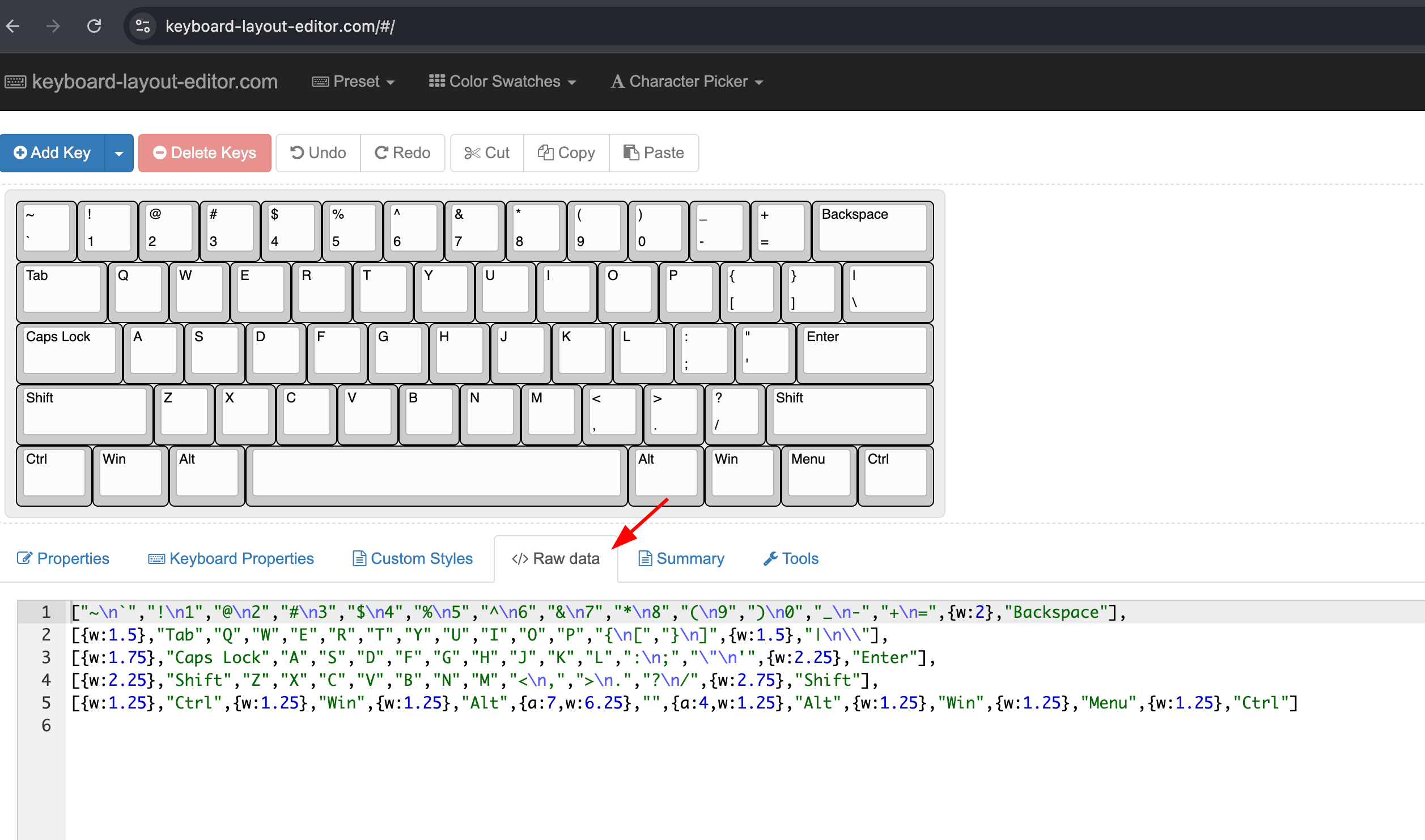
Let's use the default60 layout provided by the @tsci/seveibar.keyboard-utils package. It looks like this:
export const default60 = [
  [
    "~\n`", "!\n1", "@\n2", "#\n3", "$\n4", "%\n5", "^\n6", "&\n7", "*\n8", "(\n9", ")\n0", "_\n-", "+\n=", { w: 2 }, "Backspace",
  ],
  [
    { w: 1.5 }, "Tab", "Q", "W", "E", "R", "T", "Y", "U", "I", "O", "P", "{\n[", "}\n]", { w: 1.5 }, "|\n\\",
  ],
  [
    { w: 1.75 }, "Caps Lock", "A", "S", "D", "F", "G", "H", "J", "K", "L", ":\n;", "\"\n'", { w: 2.25 }, "Enter",
  ],
  [
    { w: 2.25 }, "Shift", "Z", "X", "C", "V", "B", "N", "M", "<\n,", ">\n.", "?\n/", { w: 2.75 }, "Shift",
  ],
  [
    { w: 1.25 }, "Ctrl", { w: 1.25 }, "Win", { w: 1.25 }, "Alt", { a: 7, w: 6.25 }, "", { a: 4, w: 1.25 }, "Alt", { w: 1.25 }, "Win", { w: 1.25 }, "Menu", { w: 1.25 }, "Ctrl",
  ],
];
Now, update index.tsx to use this layout. We also need to expand our rowPins and colPins to match the requirements of a 60% keyboard (typically 5 rows and up to 15 columns).
import { PICO } from "@tsci/seveibar.PICO";
import { type KLELayout, KeyMatrix, layouts } from "@tsci/seveibar.keyboard-utils";

// We'll need more rows and columns for a 60% keyboard
const rowPins = ["net.ROW0", "net.ROW1", "net.ROW2", "net.ROW3", "net.ROW4"];
const colPins = ["net.COL0", "net.COL1", "net.COL2", "net.COL3", "net.COL4", "net.COL5", "net.COL6", "net.COL7", "net.COL8", "net.COL9", "net.COL10", "net.COL11", "net.COL12", "net.COL13", "net.COL14"];

export default () => (
<board>
  {/* Place the Pico */}
  <PICO
    name="U1"
    pcbX={-150} // Position Pico to the left
    pcbY={20}
    layer="bottom"
    pcbRotation="90deg"
    connections={{
      // Connect Pico pins to our row/column nets
      GP15: rowPins[0], // Row 0
      GP16: rowPins[1], // Row 1
      GP17: rowPins[2], // Row 2
      GP18: rowPins[3], // Row 3
      GP19: rowPins[4], // Row 4
      GP0: colPins[0],  // Col 0
      GP1: colPins[1],  // Col 1
      GP2: colPins[2],  // Col 2
      GP3: colPins[3],  // Col 3
      GP4: colPins[4],  // Col 4
      GP5: colPins[5],  // Col 5
      GP6: colPins[6],  // Col 6
      GP7: colPins[7],  // Col 7
      GP8: colPins[8],  // Col 8
      GP9: colPins[9],  // Col 9
      GP10: colPins[10],  // Col 10
      GP11: colPins[11],  // Col 11
      GP12: colPins[12],  // Col 12
      GP13: colPins[13],  // Col 13
      GP14: colPins[14],  // Col 14
    }}
  />

  {/* Place the KeyMatrix */}
  <KeyMatrix
    layout={layouts.default60}
    rowToMicroPin={rowPins}
    colToMicroPin={colPins}
    pcbX={25} // Position matrix to the right
    pcbY={10}
  />
</board>
)
With this setup, you can easily swap default60 with any other KLE layout JSON data to generate different keyboard PCBs!
Next Steps
- Firmware: You'll need firmware (like KMK, QMK, or ZMK) for the Raspberry Pi Pico to scan the matrix and act as a USB keyboard. Try using MicroPython with the Pico!
- Export: Use
tsci exportor the download button in the web UI to get Gerber files for manufacturing. - Manufacturing: Order your PCB from a manufacturer like JLCPCB or PCBWay. See our guide on Ordering Prototypes.
- Assembly: Solder the components (Pico, diodes, key switches) onto your manufactured PCB.
Happy building!